Saturday, January 29, 2011

In Circuit Programmer (ISP) How To: Atmel AVRISP mkII

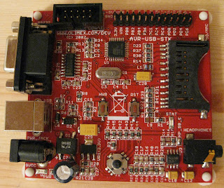
So far in our tutorials on setting up and programming the AT90USB162 development board we've taken advantage of the built-in loader via USB and dfu-programmer.  Loading code via USB is convenient, on the other hand there are a number of things that can't be done via USB and the dfu-programmer software.  AVR microcontrollers in addition to having flash memory (where your program is stored) and EEPROM (where your data is stored) also have between one and four configuration bytes as well as a three device signature bytes.  In order to read and write these bytes you need to use an In Circuit Programmer or "ISP" for short.  There are a huge variety of programmers that support AVR microcontrollers for purposes of this tutorial we will discuss Atmel's AVR ISP mkII programmer.  There are two types of ISP header commonly used on AVR boards, 2x3 and 2x5.  If you have a board, like our AT90USB162 board, with a 2x5 header you will need to buy an adapter to connect the 2x3 connector on the mkII with your board.  Sparkfun.com sells 2x3 to 2x5 adapter for $6.  Once you have your mkII, Adapter, and board attach the mkII to the board and then to your computer via a USB cable.  You will also need a second USB cable or 9v power supply to power your development board.  The mkII will *not* supply power to your AVR and if you don't power it separately programming the device will fail.

Now that we have the hardware hooked up it's time to setup the software to drive the mkII.  There are a couple pieces of software that will drive the mkII in Linux we'll be using AVRDude for this tutorial.  First you will need to get the source code for avrdude.  At the time of writing the latest version is 5.10.  Next we'll untar, configure, and compile as follows...

tar -xzvf avrdude-5.10.tar.gz
cd avrdude-5.10
./configure
make
sudo make install


To test that everything is working correctly lets read the device signature bytes using the following command...

avrdude -p at90usb162 -c avrisp2 -P usb -U signature:r:signature.txt:h


Avrdude sometimes takes a moment to complete when it does the result of the above command should be a text file, "signature.txt", containing three hexadecimal values corresponding to the signature bytes of your AVR chip.  Breaking down the above command the -p option specifies the type of AVR we are programming, the -c specifies the type of programmer, the -P specifies the way the programmer is connected to the computer and the -U specifies the operation to be performed.  The avrdude man page gives a listing of supported AVR chips and programmer devices and their associated command line option.

The last part of the avrdude command, the -U may look a little complex but it's simple once we break it down.  There are four parts to it each separated by a colon.  The first part specifies which of the locations of the AVR's memory will be operated on, common values are eeprom, flash, efuse, hfuse, lfuse, lock and signature.  A full list of values is in the man page.  The next field specifies the operation, either r, w, or v which stand for "Read", "Write", and "Verify".  The third field is the name of a file to be used on either input or output depending on the specified operation.  The last field is the format of the input / output file.  Common options for the format are either "h" for hexadecimal or "i" for Intel Hex format.  The code we loaded using dfu-programmer is previous tutorials was in Intel Hex format and the same format is supported by avrdude.

We can use avrdude instead of dfu-programmer to flash the AVR as follows.  For this example we'll use the code from the "Hello World" example.  Build the example code.  The output should be a file called "light.hex".  The following avrdude command will flash your AVR with the light.hex code...

WARNING: Using the ISP to flash your AVR will delete the USB boot loader code and dfu-programmer will no longer work.

avrdude -p at90usb162 -c avrisp2 -P usb -U flash:w:light.hex:i


The other common task you may need to do and one of the main reasons you will need an ISP is to read and write the "fuse" and "lock" bytes.  These configuration bytes configure various options like the clock divider as well as the code protection on the AVR.  The exact purpose of each of the bits within these bytes is described in the AVR's datasheet.  For the AT90USB162 the relevant information is in Chapter 25, titled "Memory Programming".

Of particular note is bit seven of the low fuse (aka: lfuse) byte, this is the CKDIV8 bit.  When programmed this option divides the system clock rate by 8.  AVR's come with this fuse bit programmed by default so even though the AVR data sheet says that the internal oscillator runs at 8Mhz that is before it is divided down.  That means that out of the box AVR's have an effective clock rate of 1Mhz.  (Note: the clock rate can also be effected by the System Clock Prescale Register, "CLKPR")  The exact clock rate your AVR runs at will be important when you start doing more complex programming tasks that involve precise timing such as serial communications.  The following avrdude command will read the low fuse byte...

avrdude -p at90usb162 -c avrisp2 -P usb -U lfuse:r:lfuse.txt:h


After running the above command the value of the low fuse byte will be stored in the file lfuse.txt as a hexadecimal number.  The default value for an AT90USB162 will be 0x5E.  In binary form 0x5E is 01011110 the left most bit is bit 7 and corresponds to the CKDIV8 bit discussed earlier. To disable the CKDIV8 option we would reprogram the lfuse to 11011110 or 0xDE.  It's important to note that the AVR data sheet uses the terms "programmed" and "unprogrammed" to denote the two states of the fuse bits.  Perhaps confusingly, "programmed" refers to a 0 value for the bit while "unprogrammed" refers to a value of 1.  To modify the lfuse byte use the following command. 

avrdude -p at90usb162 -c avrisp2 -P usb -U lfuse:w:0xde:m


In this case instead of giving a file name we are giving the value to write on the command line itself.  The "m" given for the 4th parameter of the -U argument means that the 3rd parameter to -U is the actual value to write to the lfuse and not a file name to read from or write to.
Note: There seems to be a bug in avrdude that gives the error "avrdude: fileio: invalid operation=0" if you try to write fuse values by reading them from a file, ie: lfuse:w:somefile.txt:h instead of using the "m" command line format as we did above.

That covers the basics of how to use an In System Programmer (ISP) to program and read flash, EEPROM, and configuration bytes from your AVR.

Saturday, October 23, 2010

AT90USB162 Atmel AVR Interrupts

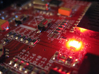
In order to do most anything useful your micro controller is going to have to interact with the external world. For example instead of just blinking an led you might want to turn on the led when the user takes an action like manipulating the joystick or inserting a memory card. There are two ways you could go about doing this. You can either use a method called polling, meaning you constantly loop and check if some action had happened, but this is in efficient. The better way to achieve this result is through the use of interrupts. An interrupt is like an alarm you set it and then forget about it and it alerts you when some event you were interested in happens. In this example we will use an Olimex AVR-STK-USB board and use an interrupt to turn the on board led on and off when a memory card is inserted into the MMC slot.

To start we need to look at the board schematic and determine how the MMC slot is wired to the micro controller. The schematic shows the MMC slot in the upper right corner. Notice that pins 13 and 15 on the MMC slot are labeled "cp1" and "cp2". "cp", in this case stands for "card presence". Examining the schematic further we see that pin 15 is wired to ground with a resistor and pin 13 is wired to power and is also labeled "cp" indicating it is connected to the micro controller. Looking at the micro controller block in the schematic pin PD1 is also labeled "cp" so we can conclude that this is pin connected to the card presence circuit on the MMC slot.

Judging from the schematic we can conclude that PD1 will be a logic high when there is no card and logic low when a card is inserted. You can test this theory for yourself using a multi meter. Set up your meter to measure DC voltage. Attached the black prob to the ground pin and the red prob to the PD1 pin. Power the board and the meter on. The meter will read 3.3 volts. Now insert a card and watch what happens. With a card inserted your meter should read near zero volts.

Next we need to figure out how the interrupt mechanism of the micro controller works. The relevant documentation is in chapter 12 page 84 of the AT90USB data sheet. The interrupt documentation for the avr-libc library is also helpful reading. Note: PD1 also happens to be the same as INT1 or External Interrupt #1

From these two documents we learn that the interrupt can be programed to trigger in four different ways outlined in table 12-1. We want it to trigger whenever there is any change in the value of PD1 so we will need to set ISC11 to zero and ISC10 to one in the EICRA register. Also the the INT1 bit in the EIMSK register will need to be set to enable external interrupt #1. Putting it altogether this is what the code looks like.

#include <avr/io.h>
#include <avr/wdt.h>
#include <avr/sleep.h>
#include <avr/interrupt.h>

#define MMC_IS_PRESENT() (!(PIND & _BV(PIND1)))
#define LED_ON() (PORTD |= _BV(PD4))
#define LED_OFF() (PORTD &= ~_BV(PD4))

int main(int argc, char **argv) {

/* disable the watch dog timer */
MCUSR &= ~_BV(WDRF);
wdt_disable();

/* setup card presence input */
DDRD &= ~_BV(DDD1);
PORTD &= ~_BV(PD1);

/* setup interrupt */
EICRA |= _BV(ISC10);
EICRA &= ~_BV(ISC11);
EIMSK |= _BV(INT1);

/* setup LED in correct state */
DDRD |= _BV(DDD4);
if (MMC_IS_PRESENT()) { LED_ON(); }
else { LED_OFF(); }

sei(); /* enable interrupts */
while(1) { sleep_mode(); }

return 0;
}

/* Interrupt routine */
ISR(INT1_vect) {
if (MMC_IS_PRESENT()) { LED_ON(); }
else { LED_OFF(); }
return;
}


Full code with makefile is available on Github A good exercise is to try modifying the above code to also turn the led on whenever the joystick is clicked.

Monday, August 3, 2009

Hello World, Getting Started with the Atmel AVR AT90USB

Once you've built your AVR tool chain for Linux you're probably chomping at the bit to write your first program. A student's first assignment on any new computer system is usally to construct the proverbial "Hello, world." program. On a micro controller like the AT90USB162 the academic equivalent is manipulating the on board LED.

Our first step is to figure out how the LEDs on your board are wired to the micro controller. In my case I'm using the Olimex AVR-USB-STK dev board sold by Sparkfun Electronics. The data sheet for the board is available on the Sparkfun site and the applicable information is on page 7. You'll notice this board has one LED and it is connected to the pin labeled "PD4". Now we go an look at the micro controller data sheet from Atmel to see how to drive that pin in software. This board has the AT90USB162 variant of the chip so we need to look at the AT90USB162 version of the data sheet. The section we are most interested in is 11.2.1 discussing configuring the pin as a general purpose digital io port. In this case there are two applicable memory mapped io registers, DDRxn and PORTxn, that control the behavior of the pin (Note: a grouping of 8 io pins is referred to as a "port"). This being an 8-bit micro controller each register is 8 bits wide. The "xn" portion of each registers name refers to "port x, bit n". That is to say there are multiple 8 bit wide io registers and each bit of a given register controls a different physical pin. Further more the direction of the pin, input vs. output, is configured with the DDRxn register and the value can be read / written with the PORTxn register.

The next question is how do we access these PORTxn and DDRxn locations. Luckily AVR libc defines constant for each chip so we don't have to look up all the memory locations in the data sheet. If you look in the AVR libc header files (Note: on my system these files are located in /opt/avr/avr/include/avr) you will see a number of .h files corresponding to various AVR families and individual chips. For the AT90USB162 there is a .h file named iousb163.h but if we look in there we find that it also includes the file iousbxx2.h which contains the majority of the definitions. If we seach for "PORT" within iousbxx2.h we eventually find definitions for PORTA, PORTB, PORTC and PORTD. After each port definition are individual pin definitions. Looking at PORTD you may notice pin 4 is defined as "PD4" which matches the name of the LED's pin on the schematic for our board.

So now we know all the basic information we need to write our program lets put it all together.

#include <avr/io.h>

int main(int argc, char **argv) {

DDRD |= _BV(DDD4); /* set pin as output */
PORTD |= _BV(PD4); /* set pin to 1, high */

while(1);

return 0;
}

The _BV() macro is the equivalent of writing, (1<<PD4). Next we'll want to compile our program and prepare it for uploading to the MCU as follows.

avr-gcc -g -Os -mmcu=at90usb162 light.c -o light.elf
avr-objcopy -j .text -j .data -O ihex light.elf light.hex

If you are using a different MCU than the at90usb162 adjust the -mmcu option accordingly. Also of interest is the -Os option passed to gcc, this tells gcc to optimize of program size. The objcopy step takes the gcc output and packages it in ihex format which is suitable for uploading to the MCU via dfu-programmer. This also strips the debugging information, so, even though we passed the -g option to gcc the debug symbols are not making it into the end executable. This will, however, help you later if you want to attached to the chip with a debugger device.

Now to upload the ihex file to our device. You'll want to plug in your board via USB and put it into program mode by holding the HWB button and pushing RST to reset the board (this applies to most board, boards like the Teensy are different). Next run the following commands.

dfu-programmer at90usb162 flash light.hex
dfu-programmer at90usb162 reset

make sure to change the controller type accordingly if you aren't using the 162. I've seen some instructions that also include the command "dfu-programmer at90usb162 erase" which clears the flash before uploading the new code. In my experience this command always fails quietly (returns 1 instead of 0 w/o an error message) and isn't needed except in certain cases when the code protection bit is set.

Once you issue the above commands the LED on your board should turn on and stay on. Except it doesn't, you'll notice the LED is blinking which isn't what we intended. So what's going on here. It turns out the AT90USB MCUs have a watch dog timer that is enabled by default and automatically resets the chip after a set amount of time if it isn't either disabled or reset at regular intervals. If you look at the AVR libc documentation you'll notice a function, wdt_disable(). Which one assumes should disable the watchdog timer, it doesn't, at least not by itself. On the AT90USB you need to zero the WDRF bit in the MCUSR register before calling wdt_disable() to disable the watchdog timer. So lets try our little program again only this time adding code to disable the watch dog timer.

#include <avr/io.h>
#include <avr/wdt.h>

int main(int argc, char **argv) {

MCUSR &= ~_BV(WDRF);
wdt_disable();

DDRD |= _BV(DDD4);
PORTD |= _BV(PD4);

while(1);

return 0;
}

Compile, upload and reset. Your LED should now turn on and stay on. Congratulations you just wrote your first program for the AT90USB162. The complete code example from this post including a makefile is available in theRandomBit repository on GitHub.

Monday, July 13, 2009

Atmel AVR Development in Linux

I recently acquired a AT90USB162 development board from SparkFun Electronics, a most excellent online electronics shop that caters primarily to hobbyists. For those not familiar, the AT90USB162 is one in a line of low cost 8-bit AVR micro controllers sold by Atmel that supports USB in addition to a host of other basic peripherals such as MMC/SD, audio, serial, and a joystick, to name a few. For those, like myself, that normally deal in the realm of more powerful embedded devices like the Gumstix or BeagleBoard it can take a little getting used to.

The main difference between development for the AT90USB and a more powerful chip is that the AT90USB doesn't run what most people would consider an operating system. This presents some challenges to those not familiar with this arena because things which you would normally rely on say Linux to do, for example, you now have to do yourself. For instance, the "schedular" on these chips is usually nothing more than an infinite loop with a small set of hard coded functions acting as the "tasks" that get called over and over again. Likewise, there are no drivers to abstract away hardware details. A far cry to be sure from the preemptive multi tasking operating systems to which most of us are a custom.

While we can't use Linux on these devices we can still enlist the help of GCC (targeted for AVR) along with a host of other open source software to speed up the whole process. Perhaps the most popular tool chain for working with AVR devices is a free development environment called "WinAVR". WinAVR is a GCC / Bin Utils / AVRlibC based distribution with an IDE thrown in that, as you might guess, runs on windows. Alternatively Atmel distributes their own environment, AVR Studio, which also runs on windows. While these seem to be the most popular judging from posts on internet message boards they aren't the only option. It is possible to do development directly under Linux without depending on Windows or any other non-free software. What follows are my notes on how I got my board up and running using only free software running on Linux.

The main thing I found is that while there are many good resources out there that provide hints no one site contained all the correct information in the same place and many omitted a few critical less than obvious details. Hence my motivation to document it here. Before you start you are going to want to gather recent versions of at least the following packages...
Since your system will already have native versions of GCC and Binutils installed we want to be careful not to clobber the native versions. We do this in two ways. First we keep out AVR tool chain separate from our systems by installing to a separate path and secondly all of the AVR versions of the tools will have the prefix "avr-" perpended to them.

To get started create a directory in your home directory where we will unpack all of the source code and do the compilation. I called my "avr-src". The first package we need to build is Binutils. Unpack, configure, build and install as follows.

tar -xzvf binutils-2.19.1.tar.gz -C ~/avr-scr/
cd ~/avr-src/binutils-1.19.1
./configure --target=avr --program-prefix=avr- --prefix=/opt/avr
make
sudo make install


Notice above when we invoke configure the "--program-prefix" and "--prefix" options. These are the parameters that keep our AVR tools from clobbering our system's tools. You can chose a different path than "/opt/avr" such as "/usr/local/avr" depending on your preference so long as you are consistent.

Next we'll install GCC. GCC doesn't support building within the source directory so we need to create a separate build directory to avoid errors.

tar -xjvf gcc-4.4.0.tar.bz2 -C ~/avr-src/
cd ~/avr-src/
mkdir avr-gcc-build
cd avr-gcc-build
../gcc-4.4.0/configure --target=avr --program-prefix=avr- --prefix=/opt/avr --enable-languages="c, c++" --disable-nls
make
sudo make install


A gotcha I encountered here is is not having the right libraries and headers installed. GCC requires the GNU MP and GNU MPFR libraries be installed on your host system. The easiest way to fix this is to use your Linux distribution's package system to find and install these packages. You will need both the libraries themselves as well as the "devel" versions of the package which install the header files. If your system doesn't provide packages or they are to far out of date you can google for the respective packages and build them from source. If you build from source be sure to run the ldconfig command as root so your system picks up the updated libraries before proceeding with building your AVR tools.

Two notes on the GCC configure options. --disable-nls disables features dealing with internationalization which you likely won't need on a micro controller target. --enable-languages tells configure what languages to build compilers for. In this case C and C++ will be supported on our AVR target.

Before going further we need to add out newly built tool chain to our path. If you use a Bash shell you can edit your .bashrc file and add the line "export PATH=$PATH:/opt/avr/bin" to it. Then source the .bashrc file or open a new shell so the path changes take effect.

Now we will build AVR Lib C. AVR Lib C is a stripped down standard C library targeted specifically for AVR's. It also includes a lot of AVR specific definitions for hardware registers and a handful of helpful functions to do things like manipulate watchdog timers and configure the interrupts. Build it as follows.

tar -xjvf avr-libc-1.6.7.tar.bz2 -C ~/avr-src/
cd ~/avr-src/avr-libc-1.6.7
./configure --build=`./config.guess` --host=avr --prefix=/opt/avr
make
su
make install
ldconfig
exit

Note those are back ticks surrounding "./config.guess" also if you use "sudo" or "su -" when installing you may experience errors to the effect of "can't find avr-ranlib". This has to do with the path being incorrect. Using plain su will preserve your path and avoids the error.

You now have all the tools you need to build software for the AVR target but you still need to be able to upload the software to the target device to run. Most AVR's in general require an In System Programmer (ISP) or similar special programming device. Luckily if you are using an AT90USBxxx based board it contains an on board boot loader that allows you to upload new images to it via USB using either Atmel's "FLIP" software or the open source DFU Programmer. (Note: dfu is the technical term for the standard the FLIP software implements.) So lets go ahead and install dfu-programmer.

tar -xzvf dfu-programmer-0.5.1.tar.gz -C ~/avr-src/
cd ~/avr-src/dfu-programmer-0.5.1
./configure --prefix=/opt/avr
make
sudo make install


Now we need to configure udev to allow access to your device when it is plugged in. This is controlled in /etc/udev/rules.d/ you need to create a new file in that directory called "99-dfu-programmer.rules" and add the following to it...

"""
SUBSYSTEM=="usb", ACTION=="add", SYSFS{idVendor}=="03eb", SYSFS{idProduct}=="2ffa", MODE="660", GROUP="uucp", SYMLINK+="at90usb-%k"
BUS=="usb", ACTION=="add", SYSFS{idVendor}=="03eb", SYSFS{idProduct}=="2ffa", MODE="660", GROUP="uucp"

SUBSYSTEM=="usb", ACTION=="add", SYSFS{idVendor}=="03eb", SYSFS{idProduct}=="2ffb", MODE="660", GROUP="uucp", SYMLINK+="at90usb-%k"
BUS=="usb", ACTION=="add", SYSFS{idVendor}=="03eb", SYSFS{idProduct}=="2ffb", MODE="660", GROUP="uucp"

SUBSYSTEM=="usb", ACTION=="add", SYSFS{idVendor}=="03eb", SYSFS{idProduct}=="2ff9", MODE="660", GROUP="uucp", SYMLINK+="at90usb-%k"
BUS=="usb", ACTION=="add", SYSFS{idVendor}=="03eb", SYSFS{idProduct}=="2ff9", MODE="660", GROUP="uucp"

SUBSYSTEM=="usb", ACTION=="add", SYSFS{idVendor}=="03eb", SYSFS{idProduct}=="2ff7", MODE="660", GROUP="uucp", SYMLINK+="at90usb-%k"
BUS=="usb", ACTION=="add", SYSFS{idVendor}=="03eb", SYSFS{idProduct}=="2ff7", MODE="660", GROUP="uucp"

SUBSYSTEM=="usb", ACTION=="add", SYSFS{idVendor}=="03eb", SYSFS{idProduct}=="2ff4", MODE="660", GROUP="uucp", SYMLINK+="at90usb-%k"
BUS=="usb", ACTION=="add", SYSFS{idVendor}=="03eb", SYSFS{idProduct}=="2ff4", MODE="660", GROUP="uucp"

SUBSYSTEM=="usb", ACTION=="add", SYSFS{idVendor}=="03eb", SYSFS{idProduct}=="2ff3", MODE="660", GROUP="uucp", SYMLINK+="at90usb-%k"
BUS=="usb", ACTION=="add", SYSFS{idVendor}=="03eb", SYSFS{idProduct}=="2ff3", MODE="660", GROUP="uucp"

"""

You may need to change the GROUP setting to be a group you are a part of instead of uucp. What this file does is tell udev how to present your device within sysfs and what permissions to assign to it. This file will cover a number of Atmel AT90USB boards based on their vendor and product id's. You can figure out the vendor and product id by using the lsusb command when your board is plugged in and in program mode. If your board isn't covered by the above just add another section with the correct vendor and product ids.

Once you've added the udev configuration file as root run the command "udevcontrol reload_rules" to pickup the changes.

To test that this worked plug your board in via USB and put it in programming mode. On my board that means holding down the "HWB" button and then pushing "RST" to reset the board. You will see a new device connected in the dmesg output and lsusb will also show the connected device. Now you should be ready to run dfu-programmer. We'll query the board for it's bootloader-version to test things out.

dfu-programmer at90usb162 get bootloader-version

Replace "at90usb162" with what ever chip your board has. If you get a error message like "dfu:programmer: no device present" then your udev configuration is likely incorrect or you aren't part of the right group to access the device.

At this point you have everything you need to start developing. Good reference resources can be found at Atmel's website in the form of data sheets, and the AVR Lib C site. There is also a Freely available USB stack called LUFA that has a lot of good demo code. Atmel provides some example code but it's a bit of a mess.

Monday, September 8, 2008

N Queens Implmented With Bits...

Here is a pretty fast nQueens implementation I wrote about 5 years back. It uses bits to keep track of each queen's lanes of attack. This approach limits the size of the board you can use to n <= (b + 1)/2 where b is the number of bits in the data type used for the bit arrays. This particular implementation uses 3 separate bit arrays one each for the x, diagonal x and diagonal y axis. I've seen solutions that are even faster than this one which squeeze all of the bits into a single 64-bit type. The basic idea here is that each queen in addition to having an x and a y coordinate also has a dx and dy coordinate. For there to be no conflicts no two queens can share a coordinate in any of the 4 axises.
/*
* Fast N Queens solution using bits.
* Copyright (C) 2008 Pete M.
*
* This program is free software: you can redistribute it and/or modify
* it under the terms of the GNU Affero General Public License as published by
* the Free Software Foundation, either version 3 of the License, or
* (at your option) any later version.
*
* This program is distributed in the hope that it will be useful,
* but WITHOUT ANY WARRANTY; without even the implied warranty of
* MERCHANTABILITY or FITNESS FOR A PARTICULAR PURPOSE. See the
* GNU Affero General Public License for more details.
*
* You should have received a copy of the GNU Affero General Public License
* along with this program. If not, see <http://www.gnu.org/licenses/>.
*/
#include <stdio.h>
#include <sys/types.h>

#define MAXN 12
#define N (MAXN - 1)

#define MARK(a,bit) (a | (1 << bit))
#define TEST(a,bit) (a & (1 << bit))

static void placeQueen(u_int32_t y, u_int32_t x, u_int32_t dx, u_int32_t dy);
static void printSolution();

static int solution[MAXN];

int main() {
placeQueen(0, 0, 0, 0);
return 0;
}

void placeQueen(u_int32_t y, u_int32_t x, u_int32_t dx, u_int32_t dy) {
u_int32_t xpos;
u_int32_t dxpos;
u_int32_t dypos;

for(xpos = 0; xpos <= N; xpos++) {
dxpos = xpos + y;
dypos = N + xpos - y;
if(!(TEST(x, xpos) ||
TEST(dx, dxpos) ||
TEST(dy, dypos))) {
solution[y] = xpos;
if(y == N) {
printSolution();
}
else {
placeQueen(y+1, MARK(x, xpos),
MARK(dx, dxpos),
MARK(dy, dypos));
}
}
}
}

void printSolution() {
u_int32_t i;

for(i = 0; i <= N; i++) {
printf("(%d,%d)", i, solution[i]);
}

printf("\n");
}
Of course there are other solutions as well using arrays, pointers, etc...

Saturday, April 5, 2008

The What and Why...

This being my first entry I think it appropriate to briefly touch on some background, not because it is particularly interesting, but because it will give context for what follows.

I've wanted to start posting for the better part of the past year. My main motivation was and is to provide a purpose for my tinkering with technology. I'm a computer scientist by trade but my interests often lead me beyond the familiar realm of software. Surveying my desk I'm reminded of countless projects, started, but not entirely finished. The primary reason for this isn't so much a lack of time as it is an absence of purpose for further effort. My initial drive is usually to satisfy a curiosity which often happens before the point of "completion" as one might traditionally think of it. That is, to say, once I see something is possible I loose interest and move on. Which brings me back to my motivation for writing here. My hope is that by documenting my tinkering I'll provide a further purpose to finish what I start.

This perhaps raises the question, of what specifically I'll be writing about? After all, "technology" is an infinitely broad subject. To answer I would say, the question you should be asking, having read the above paragraph, is, "what's on your desk?" Given the greater descriptive value of pixels over words, here is a picture of my desk. I must admit this photo is slightly contrived, I do own shelves. My desk isn't usually this cluttered, though it is often short of a clear slab. None the less, you can see there are a lot of random things in this picture, embedded computers, a bar code scanner, RF id readers, GPS and wifi antennas, iPods, and computers running the Linux, Windows, and Solaris operating system to name a few. In fact, the desk itself is a mash-up of a chest of drawers from Ikea conjoined with a slab of wood and steel pipes from The Home Depot.

Besides the purpose of this Blog, this photo also serves to illustrate its' title, "The Random Bit". Which is to say, simply, I plan to write about a variety of different stuff. It seems silly, but lack of a suitable title was the main obstacle to me starting this sooner. Despite intending to begin a number of times before now, I could never get past those first words, I think these three capture the theme well.

If there is something you are particularly interested in learning more about leave a note and I might oblige by tackling that first. Otherwise, readers or more probably just the Google crawler will be at the mercy of my scattered interests.